POWERING
UP THE RECORDER
Turning
on the Recorder
Open the control
panel door by gently gripping the recessed area at the right side
of the door and slowly pulling down.
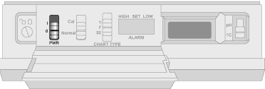
Turn the recorder on by moving the power switch located on the
control panel to the ô|ö position. Refer to Figure 3-1 for the
location of the switch. |

Figure 3-1. Power Switch
|
You then hear
1 beep and the LCD display shows the following:

Figure 3-2.
First LCD Display
The displays in Section
3.2 come up quickly once you turn on the recorder. Be prepared to write
down the codes as you see them on the recorder display. You can then compare
the codes your recorder displayed with the probe label as described below.
After the two groups of codes are displayed, the recorder continues with
its sequence, and the pens move. More details are provided in Sections
3.3 and 3.4.
Recording
the Code Numbers
A two-character temperature
code made up of numbers and/or letters 0, 1, 2, 3, ... , 8, 9, a, b, and
c appears. An example is shown in Figure 3-3; the numbers will vary:

Figure
3-3. Temperature Code
|
|
Then, a single-character
pH code, a number or letter 0, 1, 2, 3, ... , 8, 9, a, b, or c, appears.
An example is shown in Figure 3-4; the numbers will vary:

Figure
3-3. pH Code
|
|
Final
Display Mode
After the
pH and temperature codes appear, the LCD displays the current fluid temperature
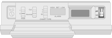
in ░C or the fluid pH, depending on the position of the display selection
switch (refer to Figure 3-8).
Initially, the pH recorder pen moves to the right a short distance
and then moves to the left to the zero position. The temperature
pen follows. Then, both pens, one at a time, move to the positions
which correspond to the current temperature and pH.
At this point, the recorder is ready to use. |
 Figure
3-8. Display Selector Switch
|
|